Peak current detector error improvement 2021-10-09
Motive
Self made peak current detector uses 0.1Ω for detecting which has 5% allowance error. Enoki would like to decrease the error.
Summary
Enoki soldered a chip resistor 0.1Ω 1% 1W. So detecting current error decreased to 1%.
Axial vs chip resistor
The peak current detector is assembled on a universal through hole board.
The present detecting resistor is 3W axial with gold band meaning 5% allowance error.
As Enoki was anxious about soldering a chip resistor on the universal board, and hesitated to use SMD (Surface Mounted Device) parts.
Enoki bought 50 pieces of 2512 size for a try at AliExpress.
Resistor material
The previous detecting resistor material was metal oxide that has high TCR (temperature coefficient of resistance) 300 ppm/°C. While metal film resistor is 50 ppm.
Soldering 2712 chip
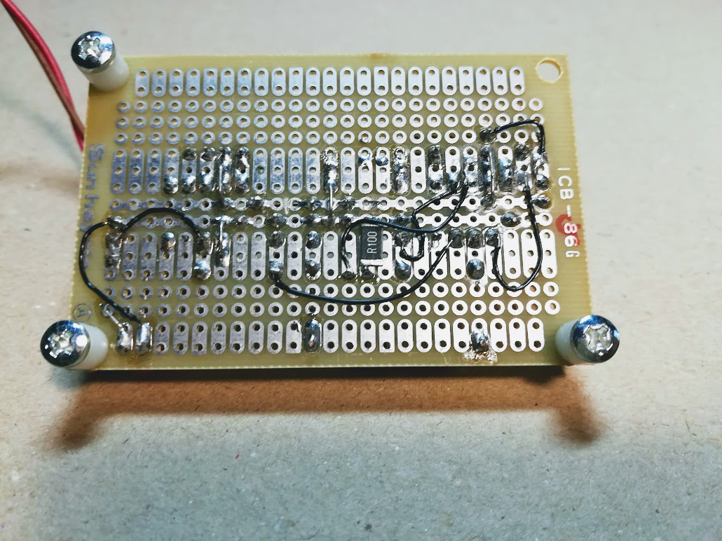
Enoki soldered the chip resistor on inside of the board as shown in Photo1.

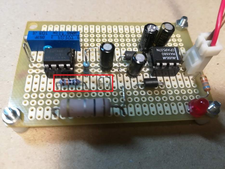
Enoki built a lead wire loop pin for inflow current as shown in Photo2 and removed 1/8W 1Ω resistor.
A measurement example
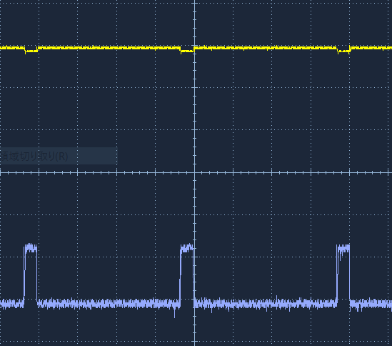
Enoki measured power supply 5V5A output current as shown in Figure1.

OP output resistor 100 kΩ saturated at 4.5V at first as shown in Photo2.

So DSO SDS1102 measured the dropout voltage direct as shown in Figure1.
The peak voltage was 59.0 mV (CH2 50mV/div), so the peak current was 0.59A. CH1 yellow 500mV/div was power supply output voltage.
The output sagged a little bit because of current detecting dropout voltage.
The current period was 2.03s
Conclusion
Range over
As Op amplifier gain is 101 and power supply is 5V, detecting maximum current is 0.45A.
To get more range ability, one is to lower gain, another is to increase power supply
voltage.
Lower gain:
another output resistor and switch
Increase power supply voltage:
another power supply and exchange of LED current limiter
resistor.
S/N
Op is excellent low pass filter with 20dB gain. It is easy and sure to read peak current through
Op.