Motive
Enoki found that a Chinese DC-DC converter could not regulate output voltage constantly. And the standby current flows big a few mA. Enoki had confirmed the standby current was less then 1 uA. So Enoki tried to measure 3.3V Holtek DC-DC characteristics.
Summary
The Holtek DC-DC regulates within allowance of MPU, if you choice the electronic parts properly.
経緯目的
ある中国製 DC-DC コンバータは 3.3V の正規出力をレギュレートできなかった。
Summary
部品を適切に選択すれば,Holtek DC-DC は正確にレギュレートする。
Holtek 3.3V DC-DC converter test 2020-01-14
Field endurance and Feautres
Enoki had adopted the 3.3V Holtek DC-DC converter[1] for driving XBees about 3 years. Now one of the converters works on the water level sensor. The features as follows,
Measurement system and method

I built DC-DC circuit on a working board, and replaced the Chinese one flowing into more than a few standby current. Figure 1 shows the block diagram of the measurement system. Variable Voltage power supply is Enoki's scratch to adjust voltage with 15 rotation trimmer more than 1.25V to 10V.
The input current was measured by DMM Sanwa PC510. The input and output voltage were measured by DSO TDS2002. I read the input voltage sag frequency by DSO cursor and the mean output voltage.
I loaded fixed resistors such as 1/4W 3.3k, 330, 150 Ω, 2W 100 Ω.
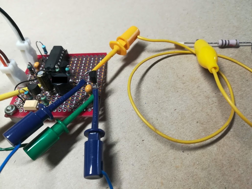
The current flows into the left connector through the ammeter. The left yellow IC clip detects the input voltage. The blue IC clip detects the output voltage. The right IC clip connects to the end of the load resistor.
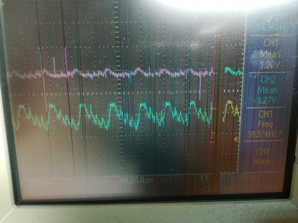
When output capacitor adds another one, the charging current wave varies the frequency and DSO cannot trigger at last.
The measurement result
Evaluation and problems
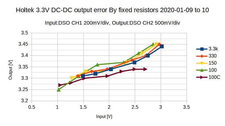
All of the output errors were a little bigger, when output capacitor was ceramic as shown in Figure 1. But the error decreased with an additional capacitor. I think that ESR of electrolytic capacitor decreases the positive error.
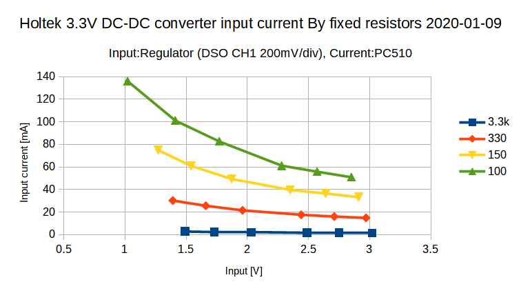
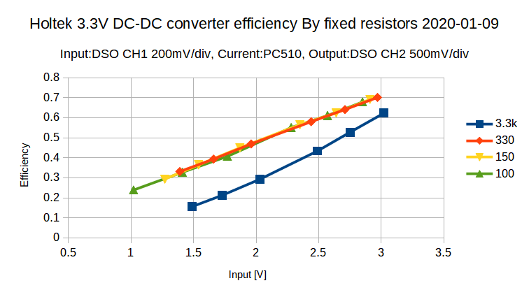
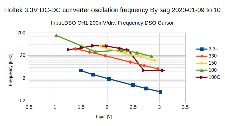
Legends of 3.3k, 330, 150 and 100 are fixed resistors each. 100C means in case of additional electrolytic capacitor.
Naturally input current increases, when input voltage lowers as shown in Figure 3.
Figure 4 shows the efficiency of 3.3k, 330, 150 and 100 Ω which are equivalent to 1, 10, 22 and 33 mA nominal each. The converter works little efficient less than 1mA.
Figure 5 shows oscillation frequency, when input voltage lowers. The frequency reaches about 200 kHz at input 1V in case of 33 mA nominal. The specification sheet describes that the maximum frequency is 200 kHz. The duty of cycle may change, when more current flows at input 1V.
The DC-DC converter stands by less than 1uA, though a few breed current flows in case of a Chinese DC-DC converter. The ratio is 1/2000.
Concerning the measurement method, Ammeter PC150 has input impeadance of 33 Ω. So it happened to be able to work at 1V less than 1.25V which is the lower minimum output of the regulator.
And it cannot adjust output voltage well, while the voltage equivalent to one turn is 0.67 V. But it would not be enough to get reproducibility.
I thought that I had better buy a Chinese programmable power supply than rebuild up my analogous power supply before. But the load regulation generates 10 mA offset, as it is big 30V/5A capacity. If the offset is a breeding current, Can I correct?Although LM723 is a traditional old linear IC for voltage regulator[2], it may be good to supply less than 3.3 or 5V for my purpose.
© enoki.net 2020 January 14
