Summary
Although a Chinese DC-DC converter cannot regulate the nominal output 3.3V correct, it could pull out 20 mA from worn out AA batteries that illuminance sensor had dissipated without DC-DC converter almost a year.
Motive
Enoki hopes that the DC-DC converter can use in the wireless water level sensor.
要約
中国製 DC-DC コンバータは 3.3V の正規出力をレギュレートできなかったが,DC-DC コンバータを内蔵しない 照度センサの電源として一年近く消耗しきった電池からは 20mA の出力が得られた。
経緯目的
当該 DC-DC コンバータがワイヤレス水位センサに使えるかテストする。
A Chinese DC-DC converter test 2019-12-05
Purchase and the specifications
Enoki bought it at Banggood.com. The specifications as follows,
Mini DC-DC 0.8-3.3V~DC 3.3V power step-up boost module, Arduino Breadboard
Specifications:
Size: about 1 × 1 × 0.7cm / 0.39 × 0.39 × 0.28 inch
pin pitch: about. 2.54mm / 0.1 "
Input voltage: 0.8-3.3V
Output voltage: 3.3V
maximum output current: 500 MA -
start voltage: 0.8V, output current: 10mA input 1-1.5V, output 3.3V 50-110mA input 1.5-2V, output 3.3V 110-160MA
input 2-3V output 3.3V 160-400MA exceeds 3V input, output 400-500MA 5V DC-DC boost module operating
frequency 150 kHz, the efficiency is 85% normal
Note:
the input voltage is maximum input range can not be greater than can not be greater than the output power for a long
time of maximum load input power, must be greater than the output power this is, the power consumption of the
module itself.
Measurement system and method

Figure 1 shows the block diagram of the measurement system. Alinco brand power supply is difficult to adjust fine output, so Enoki's scratch to generate voltage less than 1V applied this method.
All the current and voltage were measured by DMM. Sanwa PC510 and Metex P-16 have 4 1/2 digits. Sanwa SD-420C has 3 1/2 digits.
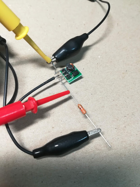
I soldered a loop wire to input VI pin, a lead wire to GND pin and a resistor lead to VO pin.
I loaded a fixed resistor as shown in Photo 1 that 10 mA flows out in case of 1/2W 330 Ω. I tried other 2W 33 Ω, 1/4W 100 Ω and 1/4W 680 Ω.
The current flows through the ammeter into by the black clip. The yellow IC clip detects the input voltage. The red IC clip detects output voltage. The clipped black clip of the other end of the resistor leads to GND.
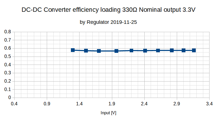
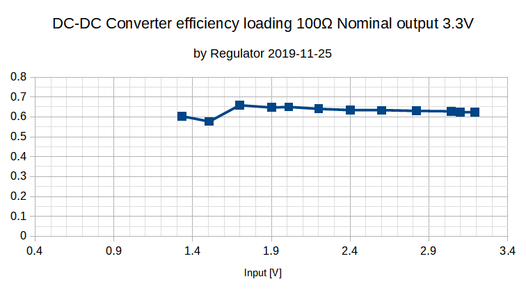
The measurement result
Evaluation and problems
I was surprised that the converter could not control the nominal output 3.3V within allowable errors to drive MPU.
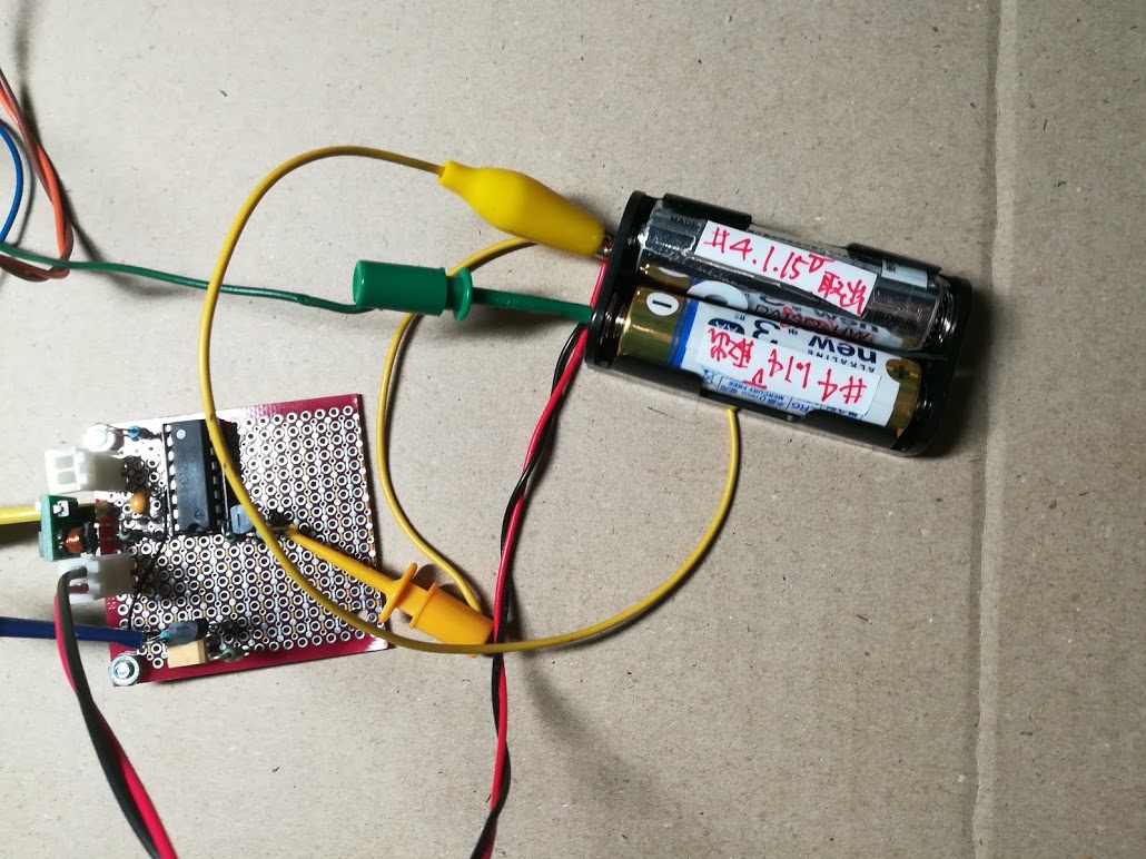
I happened to get dissipated batteries that worked I2C sensors with TWE without DC-DC converter for 302 days on December 1 2019.
I tried them on a small circuit to drive 20 mA at 3.3V as shown in Photo 2, The converter could pull up the 20 mA current.
It is useful to step up batteries input voltage for driving water level sensor, I think.
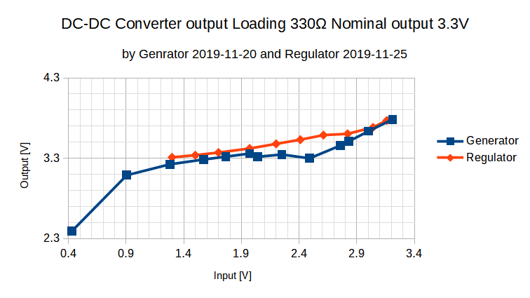
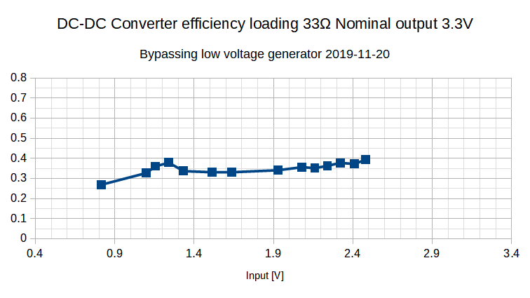
When you look at the output chart as shown in Figure 2, The generator seems better than conventional regulator that works more than 1.25 V.
But it was not correct. When I watched at the input voltage wave form by DSO, the voltage varied sharp.
The DC-DC converter works at 150 kHz, while the low voltage generator might not work at the high frequency.
It is necessary to rebuild up for much high frequency load.
And it cannot adjust output voltage well, while DC-DC converter is working at the same time. I had better buy a Chinese programmable power supply than rebuild up my analogous power supply.
© enoki.net 2019 December 5