Background
Enoki's tiny power suppy had been already added current detecting resistor 1Ω at high side before 2013. Later Enoki has replaced it for 1% tolerance metal film 0.47Ω at low side in 2020. But DMM and transistor tester measured 0.60 and 0.55Ω. Is the nominal resistance correct?
Summary
Enoki confirmed that the resistance was 0.47Ω. Enoki measured across the voltage drop inflowing constant current by the tiny PS.
How to confirm low resistance instead of DMM 2021-06-09
High side or low side
DSO can observe varying current by measuring dropout voltage across a resistor. When connecting it to high side, the voltage floats from GND. So 2-channel DSO cannot observe another signal at the same time. Because CH1 and CH2 GND is the same common.

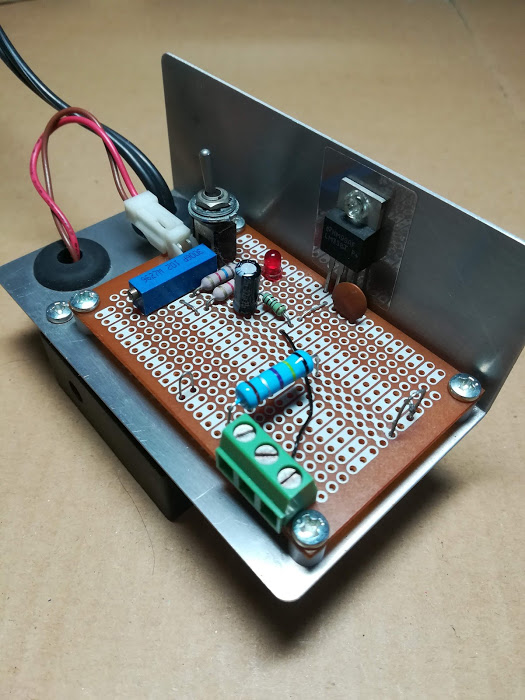
Photo1 shows the revised tiny variable voltage power supply with 0.47Ω.
Resistance by transistor tester
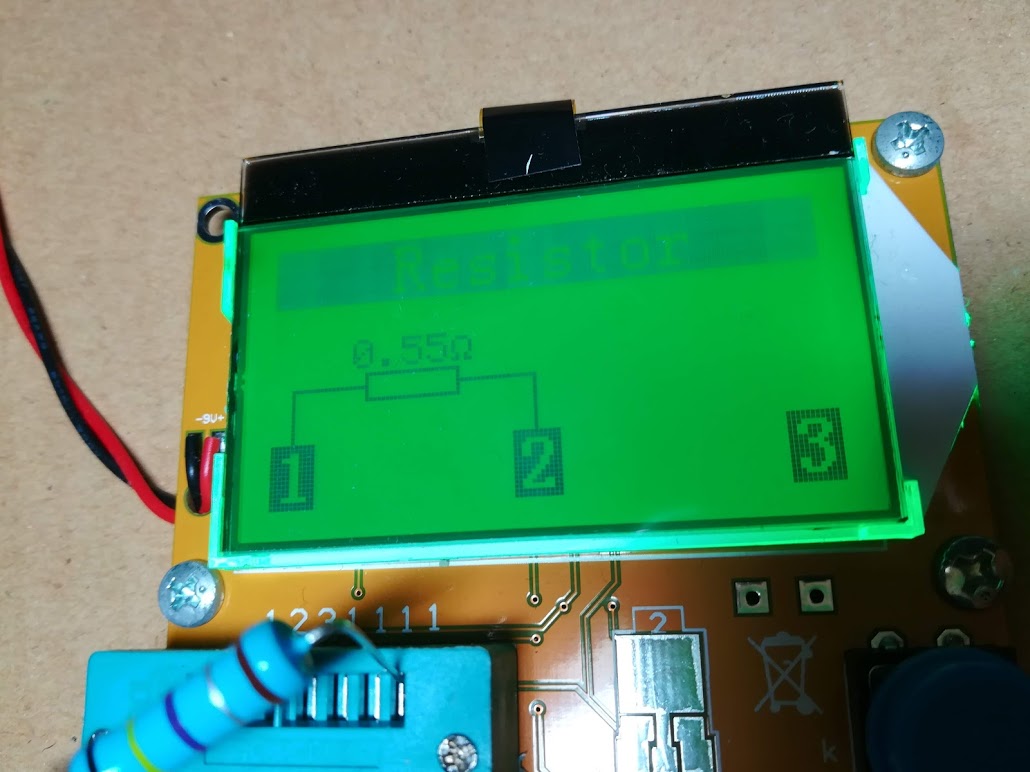
Enoki has a popular transistor tester which may be a copy of TLP-T4 etc. It measured 0.55 Ω as shown in Photo2.

Method
When DMM measures resistance, it affords current. it measures voltage including its probe leads resistance. In case of voltage measurement only, the input impedance can be very high.
Affording current another way,
the measurement can ignore leads resistance.
The result
Source 12V supplies current. DSO SDS1102 CH1 2V/div monitored the voltage. DMM PC510 measured the current.
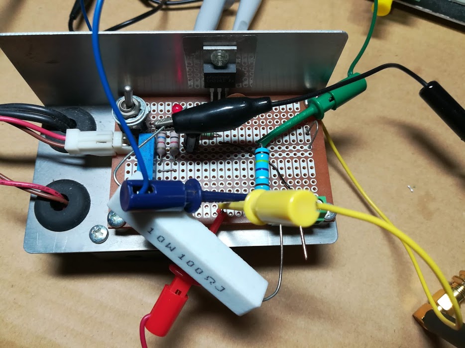
Connecting 100Ω to 0.47Ω in series, DSO CH2 500 mV/div 20ms/div measured 0.47Ω dropout voltage shown in Photo3.

Resistor value R is,
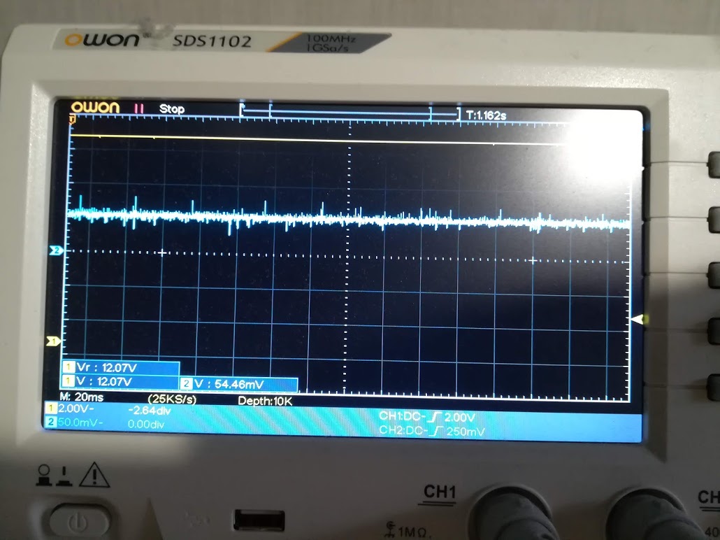
R= 54mV/114.3mA = 0.472
Photo4 shows the voltage. GND noise was nearly 0mV.
Conclusion
Enoki found that PC510 measured wrong, but why did the tester measure wrong? It has no probe leads.
Looking at the original circuit, The terminals connect to ADC directly. MPU ADC input impedance has equivalent to 1kΩ order.
Enoki thinks that the ADC input impedance is too low to measure low resistance.
Ref.
Datei: TransistorTesterVC1.png
© Enoki 2021 June 6 - September 18