Wiring for 1.75mm pitch IC
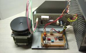
TweetI have planned making a polisher of gravel. I made a stepping motor driver as the photos show. The driver is 1.75mm pitch of ZIP IC. The IC does not fix on a usual 2.54mm pitch universal board. So I made its circuit in two universal boards. The wiring was mess for crossing wirings between boards and skew-whiff holes pattern.
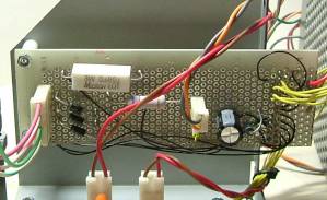
But the driver IC has a lot of function. At first it drives a bipolar stepping motor which always currents 2 coils, otherwise unipolar type currents 2 of 4 coils. And the IC can do 1/8 micro step drive at ease. I used a DIP SW for switching usual or 1/8 micro step, phase (coil) current, CW/CCW direction, and enable or not. I adopted 7555 IC for generating pulses. A variable resistor changes the driving pulse frequency from 0.66 to 8.94kHz. The drive circuit have a slide switch for jogging and a toggle switch for start/stop. I fixed the ZIP drive IC on the opposite side of the skew-whiff pattern universal board. The table shows the specifications of the drive circuit.
| Drive IC | Toshiba TA8435H |
| Pulse IC | Intersil ICM7555 |
| DIP SW | High/Low phase current 1/8 micro step CW/CCW Enable/Disable |
| Slide SW | Jog mode (40pps) |
| Toggle SW | Start or stop |
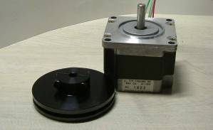
| Motor | JapanServo KH56JM2-851 Step angle 1.8° Phase current 1.3A Holding torque 5.0kgfcm |
| Heat sink | 1mm thick steel (SECC) |
The driver circuit drived the motor with no load at the range of 5.5kHz in pull-in. I applied a mass of 256g pully for inertia load. The response frequency dropped at 2.5kHz.
Biwa Lake JAPAN aboutMe© 2008-2011 Enoki