The following includes Japanese characters.
Water pump driven by PWM 水中ポンプ
TweetAbstract 概要
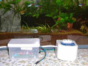
The photos shows power supply for the water pump and rebuilt PWM driver in box.
家庭で熱帯魚を飼育している。その際,適温にしたバケツ中の水( 25L )を水槽まで汲み上げるのに難儀であった。家庭用の水中 ポンプは流量が過大で水槽のソイルを攪拌し,混濁させてしまう。以前製作したPWMドライバを改造して,いくばかりの実験を 行った結果,デューティ50%はポンプ電源の発熱を著しく低下させ,連続運転を可能にした。またデューティ100%において,流量を 分流させ,適度の噴流が得られた。
Background
My family keeps small tropical fish. Although they bought a big bucket for exchanging water in aquarium tank, they found that there was no space on the table which the aquarium tank was. And it is too heavy to lift up the bucket. They thought that water pump was good. I told that the pump had too power to get proper water rate. I proposed to control the power of the pump. I calculate how power is. The height is 1 m from the aquarium tank on the table to the bucket in the floor. Considering energy conservative law of the flow control system,V12/2 + gz1 + dQ/dm = V22/2 + gz2 + dWs/dm
Condition with the same diameter of inlet and outlet, and continous law, flow velocity is the same as the inlet and outlet. There is no heat to come in and out.dWs/dm = g(z1 - z2) = 9.8 m2/s2
Power P is,P = dWs/dt = (dWs/dm)(dm/dt)
Therefore, dm/dt is flow rate. The diameter of the tube may be 1 cm. the bucket volume is 20 L. If they want the water to fill in 1 minute, The flow rate is,dm/dt = mass / time = 20 / 60 = 0.333 kg/s,
So the power is,P = 9.8 * 0.333 = 3.26 Watt
As flow rate is the product of (density)*(area)*(velocity), the flow velocity V is,V = 0.333/(1000*0.785E-4) = 4.24 m/s
I think that the velocity is high to fill still in the aquarium tank.
Look for a water pump to work
I have a window washer pump for car. It works at 12 VDC, but does not work in water. I thought that home use oil pump could work. A site shows that a pump for home use had 0.4 m lift only.[1] Japanese people use small fuel pump to transfer fuel from portable tank to cartridge tank in fan heater. We do not reserve much oil underground like Americans. We buy 20 L oil at gas station in Winter. We carry portable tanks to our home by car. In case of my home, a small lorry of fuel shop supplies our portable tanks. Toyo Pump brand has the biggest share in Japan.[2] Miyake Kagaku has the brand now.[3] Now the pum has a sensor to stop automatically. My family had used a few pumps of this auto type for 15 years. I use an old fashioned siphon now.
| Dimensions [mm] | Weight | |
| Pump | D55.5xL44, D31xL70 | 125g |
| Power supply | 75x65x47 | 350g |
I got a water pump set with power supply. The pump has a long tube. The nominal power supply is 0.8A at 8VDC. The power is 6.4W. If the working duy of the pump is less than 50%, I think taht I will get a desired flow rate.
A happening to test charging batteries
I have deloped a PWM Driver to control current of constant voltage suppy for plug heater for RC model aircraft. I will rebuild the BAT box for my experiment. I took off it form shelf. I had to trace the circuit by tester because I have lost circuit drawings and documents since HDD crash of my 400MHz PC. I found that one of the batteries showed very low voltage 3.105V at nominal 6V. The other was 5.985V. The bad one is connected with the good one with series. I tried charging the bad one, though I do not hope. There was no chargin current. While the good one got nearly 1A. A few hours later, I set up charging voltage to 6.6V. Start charging at 17:20, There is no current by power supply indicator at 8:05 the next morning. Its terminate charging voltage was 6.53V. I confirmed the current between power supply and the battery by tester. The tester showed a negligible alternate current.- Disconnect No 5 of top terminal base
- Connect PS GND terminal with the top No 5
- Disconnect No 1 of under terminal base
- Connect PS PLUS terminal with the under No 1
Check duty
| Period | Min | Max | PS |
| 51.95us | 2.86us 5.51% | 11.0us 21.2% | 6.72V |
| 51.68us | 2.85us 5.51% | 11.22us 21.7% | 8.0V |
I checked duty of pulse at max and min control volume position. Power supply is DM-310MW by Alinco. The measuring DSO is Tektronix TDS2002. I have two DSOs. I measured gate voltage of switching MOS FET.
So the motor power will be 20% of nominal power 6.4W. Is 1.2W too small?
Check the water pump lift
| Nominal | Open output | Maker | Type |
| 8V | 11.4V | SENDAK[7] | YS-30 |
| 12V | 12.6V | NAK | Mini Mk2 |
| Volt | 1V | 2V | 3V | 4V | 5V | 6V | 7V | 8V | 9V |
| I [A] | .176 | .236 | .320 | .412 | .506 | .611 | .703 | .822 | .954 |
The table shows open output voltage of power suppy for water pump. I measured them by digital multimeter, Sanwa PC510. The values fluctuates a little. They may be ripples of alternate current. I cut the motor cable of 4.5mm diameter. The innder two wires seems less than 0.2SQ. Why does the maker adopts the thick sleeve? I connected it with power supply DM-310MV and measured current by DMM PC510. I removed the tube and soaked in water of bucket. I confirmed water flow at 2V.
Capacitor rating
I connected Sendak's power supply and the water pump with my PWM driver. I began doing the test in the bucket. The pump worked at the max of pulse width duty. The jet seems less small to lift upto 1m. Several hours later, I found that a capacitor was hot. The capacitor is to absorb surg, when FET swtiches on/off. I measured the inducted voltage 25.2V. The nomimal max voltage is 50VDC. I looked into a book how to use electronic parts. I found that Vrms decreased at high frequency at sharp. Allowable voltage of 0.22uF of polyester capacitor decreases 20V from nominal 150V at 20kHz.[5] I removed the capacitor and measured the inducted voltage 60.8V. The pulse width was 3.2us. The pulse height value exceeded the nominal max voltage. I knew why the capacitor heated, inspite of working as plug heater. Back electromotive force of motor is big. To release the back electromotive force, I added a diode of IN4005 and an inlush protection resistor of 20 ohm. I removed inlush resistor for load. The resistor is not necessary because motor is inductive load. The pump does not rotate at duty of 21%. I replaced some resistors of the circuit to increase the duty. The pump rotated at the inverted duty 65.9%.
Joint of tube
| Name | ID | Sleeve | Full length | Weight |
| PVC sleeve | 18 | - | 48 | Neglible |
| Brass nipple | 11 | 29 | - | 74g |
| SUS 3/8 elbow | 13.2 | 0 | ? | 26g |
| Plastic nipple | 11 | 27 | 45.5 | 5g |
I should work the piping of the water pump as possible as least loss. The outlet demensions of the water pump are 13mm inner diameter, 18mm outer diameter and sleeve length 18mm. The total lenght of the pump outlet and the brass nipple sleeve is 47mm (18+29). I cut the sleeve 48mm and pushed the brass nipple into the sleeve, but the nipple rested at 4mm long. So there is an enlarged space of D18xL5mm. The inner diameter of the 3/8 elbo is just the size of one of my fingers.
Water head
| Duty | Diameter | Water head |
| 50% | 12mm | 40cm |
| 100% | 12mm | 180cm |
| 100% | 10mm | 40-45cm |
| 100% | 10mm | 180cm |
| 50% | 6mm | 56cm |
| 100% | 6mm | 180cm |
I looked for a suitable tube for a test at DIY shop. The shop had sold various transparent PVC tubes before. There are a few ones now. I bought 2.4m of 12x18 reinforced by net. I connected the tube with the 3/8 nipple. I measured water head by scale. The heads were 7 and 9 cm at the duty of 66 and 100 % each. The value of 100% duty was too small. I cut pump cable and added 0.1 or 1 Ohm to measure current in the motor. The DC resistance of the motor is 4.5 Ohm. The current waveform showed a big sag in positive area. I measured it averaging because of big noises. The distorted sag means that inrush current is not enough or the back electromotive force falls fast. If power supply voltage increases, inrush current simply increases. But it is very difficult to increase the power supply. If the value of the dumping resistor in flywheel circuit increases, the back electromotive force should fall fast. But be careful for heat of the resistor. The loss power is proportional to the resistance. So I increased oscillating period to 182us from the described 52us. The long period satisfies a long settling time of the back electromotice force. I also changed the circuit to fix the duty of PWM to 50%. A toggle switch alternates 50 and 100 % duty now. The switch was for start/stop.
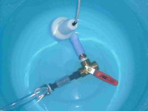
The water pump has no stop valve which a cheap oil pump has. So I fitted a 3-way valve to soak the outlet of the pump in water. The valve has a holl diameter of 6 to 7 mm in the ball. I found that a big bubble came out, when I soaked the pump assembly. The table shows the result of water head measurement. 180 cm is a champion data. The water head rather shows that the piping loss is very small than PWM circuit itself. It lifts certainly 140cm at least, when the duty switch turns on. It is enough to my family's aquarimu tank. If the 3-way vlave divides the flow and release some ratio back in the bucket, I connected the piping as shown in the photo and confirmed to control the flow and got enough water head at 100% duty. I connected transparent 10mm diameter tube with the SUS nipple. I also tried 6mm diameter tube with no divided flow that the 3-way valve was closed. It showed only 40cm of water head at 50% duty. I think that the flow was shrunk by the 3-way valve. The valve has nearly 6 mm diameter hole in the ball because diameter 7mm of drill does not pass through the hole.
I happened to run the water pump at 100% duty for an hour. The case of power supply was hotto hold in hand. While it worked at 50% duty for three hours and the case was not hot and warm.
Divide flow to control
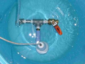
The water pump lies steady in the right photo of the piping method. Once the pump lies, it cannot absorb water of the bottom of the bucket when the inlet of the pump come out air.
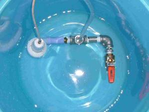
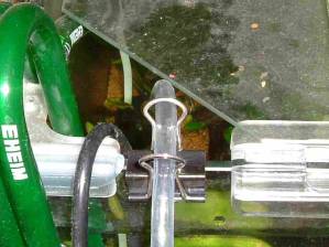
I thought how to fix a 6mm diameter tube end, when the pump continue to fill water for five minutes. The photo shows a big clip for stationary. The 8mm outer diameter fits between the wires.Remarks
I do not know why the water head showed the small value at 100% duty. It is important to increase inrush current for high water head. The oscillator always works even at 100% duty. I think that the dissipating peak current of PWM driver decreased when oscillating frequency decreased to 1/3.5. It is known that CMOS IC dissipates much power on switching. Actually the surface temperature of the IC package has decreased.
The pump dissipates 0.822A at 8VDC, when its impeller rotates freely in water. I should find that the total inductance and resistance was 9.73 Ohm at once. The inductance is more 20.6 times than 0.45 Ohm of the motor DC resistance.
Contents of rebuilding the PWM driver are,- Change inrush protection R3 1 Ohm into free wheel resistor 20 Ohm 2W
- Change time constant resistor R4 6.9k with 22k
- Change input resistor R5 10k of the oscillator with 560k
- Change delayed resistor R6 1k with 20k
- Change protection resistor R3 33k for external control into input protection resistor 1.8k for driving gate of FET
- Add a capacitor of 25V1800u
I knew how to handle a water pump this time. The water pump cannot flow any more at 100% duty, if the outlet of the pump is filled with air.[6]
[1] ビルジポンプ
[2] 灯油ポンプの製造で日本一
[3] Miyake
[4] 配管のコンダクタンス
[5] わかる電子部品の基礎と活用法 p69
[6] 動く音はしているが水が出ない
[7] センタック
Biwa Lake JAPAN aboutMe
© 2011 Enoki