Motive 経緯目的
Applying ceramic capacitor for electrolytic one, I have planned trying Holtek 3V3 DC/DC converter efficiency up for batteries to drive power supply of TWE wireless module and I2C sensor
Summary 要約
At first, to measure power efficiency I evaluated my DMMs. I worked 1A voltage regulator at 0.1V. I measured power transfer efficiency of conventional capacitor. Changing it for ceramic capacitor, I also the same measurements.
Which is better electrolytic or ceramic capacitor to drive DC/DC converter?
P = VI
Differentiating,
dP = VdI + IdV
dP/P = dI/I + dV/V
Therefore,measurement error of power is sum of current and voltage.
I always use DSO for DMM,DC accuracy of DSO is 3%. it is not good. The DSO measurement has repeatability, but cannot decrease absolute errors. I have 3 DMMs of PC510, SD-420C and P-16. They lack one to measure power. I connected an IC clip to change input and output voltage, as I learned science in junior high school.
Input power error PC510 + SD-420C = 1.5%Output power error P-16 + SD-420C = 3.3%
DMM P-16 restricts the measurement accuracy.
PC510 0.2% for current
P-16 2.0% for current
SD-420C 1.3% for voltage
Voltage regulator from 0V
I have no power supply available to adjust output near 0V. I had worked a small circuit to control below 1V 1A. So I have tried closed loop control to decrease power dissipation
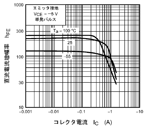
and failed. I rebuilt adopting PNP transistor that I have had 2SA1056 and 2SA562 for NPN. The new TTA004B maximum collector current is 1.5A, while 2SD553 is 7A.
But TTAA004B is cheap. TTA004B hFE breaks down around 0.7A. I decided not to work over 1A. It inflows 0.948A (PC510) @ 0.403V (SD240) in case of load 0.3Ω.
The collector loss is,
Pc = 0.951 x 3.94 = 3.75W
Thermal resistor calculus of heat sink
I have heat sinks of thermal resistor 12.5 °C/W. I estimated the thermal resistor of the heat sink and TTA004B is 19.5 °C/W. While I measured the rising temperature by Tanita TT-533 thermometer. The thermal resitor is 8.4℃/W only. The actual thermal resistor might be the intermediate value. It is difficult to measure temperature of surface body.
Electrolytic vs Ceramic capacitor
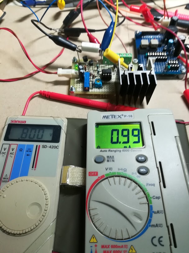
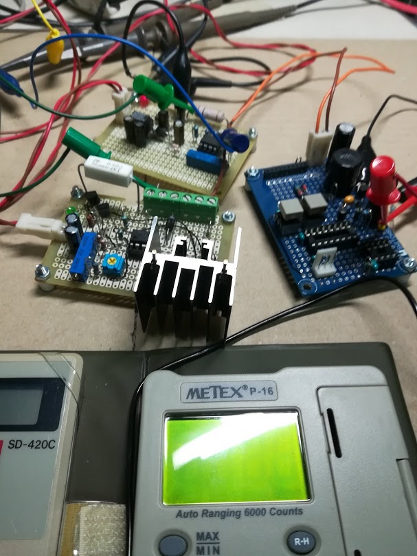
I measured input/output voltage and output current shown in Photo1. The DC/DC converter is on the blue board. You can see the blue 47uF capacitor on it.
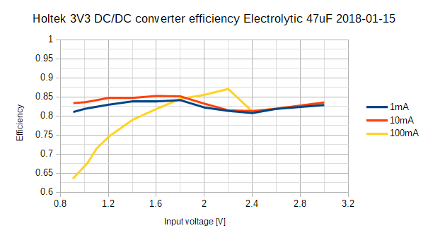
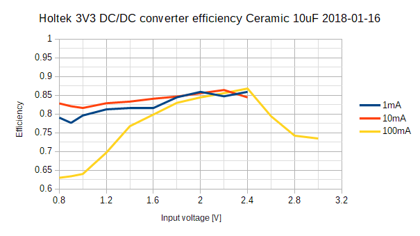
Figure2 and Figure3 show efficiency charts of electrolytic and ceramic capacitor. Fixed 3.3k, 330 and 33Ω resistor inflows 1, 10 and 100mA each approximately.
Ceramic: 200uA output
1) 100mA
Electrolytic is better except 0.8V.
2) 10, 1mA
Ceramic is better over 2.0V. It is impossible to measure inflow current because the value fluctuates.
The actual output voltage drop is shown in Figure4. The ceramic capacitor cannot control flat at 3V3 as well as electrolytic does. But ceramic drops little than electrolytic below 1.4V. The 100mA of Ceramic exceeds 3V3 over 2.4V input.
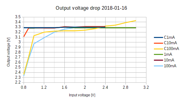
| Vin [V] | Period [ms] | Iout [uA] |
| 1.028 | 50 | 212.5 |
| 0.904 | 134 | 212.5 |
| 0.802* | 258 | 212.4 to 213.4 |
Conclusion
The ceramic capacitor 3V3 DC/DC converter cannot replace unused two series batteries, because the output voltage exceeds the maximum voltage of TWE. Single battery is preferable.
In case of 1mA and 10mA, input current is not continuous more than input voltage 2.4V. I do not know how input pulse current has a good or bad effect on battery. XBees also have been dissipating discrete pulse current while sleeping. It will not be anxious about pulse current, will it?
Table2, Table3 and Table4 show the values that PC510 and P-16 measured the same current. At a glance, it looks the values correct. But the third digit of them are uncertain. It is necessary to use more precise meters to argue 1% efficiency up/down, I think.
Ref.
Мультимер Sanwa SD420CPC510
| PC510 [mA] | P-16 [mA] | Deviation [mA] |
| 53.1 | 52.46 | -0.64 |
| 25.05 | 24.83 | -0.22 |
| 11.40 | 11.41 | 0.01 |
| 4.86 | 4.82 | -0.04 |
| PC510 [mA] | P-16 [mA] | Deviation [mA] |
| 6.35 | 6.3 | -0.05 |
| 9.62 | 9.55 | -0.07 |
| 67.3 | 66.7 | -0.6 |
| 99.3 | 98.1 | -1.2 |
| 101.4 | 100.4 | -1 |
| PC510 [uA] | P-16 [uA] | Deviation [uA] |
| 983 | 989 | 5 |
| 637 | 641 | 4 |
| 105.7 | 105.5 | -0.6 |
| 99.3 | 98.1 | -1.2 |
| 101.4 | 100.4 | -0.2 |
© Enoki 2018 January 19