Improved interface of semiconductor temperature sensor and App TDS298
TweetI measured my room temperature for a long time to evaluate two kinds of semiconductor tempeature sensors on my mother board. I assembled and soldered the two temperature sensors with 1mm gap on my mother board. I show a chart drawn by my app Slip21. I set offset value of Slip21 not to overlap the curves each other. The two sensors acutually should indicate the same temperature. I found noise of M3 is much bigger than M4. I looked into the noise by DSO Tektronics TDS310. The DSO averaging showed to suppress the noise well. I wrote it in my blog and you see detail in Japanese. I decided to amplify M3 by OP amplifier. I have LM358 and used it. I designed its circuit carefully because LM358 bias current is big and used a few resistors and a capacitor in my part box. I found MCU averaging process is useful for suppressing the semiconductor noise. I stopped fast scanning of A/D and adopted conventional scanning. I think it would be better. You can calculate the scanning time reading the MCU manual. I measured that the scanning time is 31.25kHz. It is far faster than varying temperature.
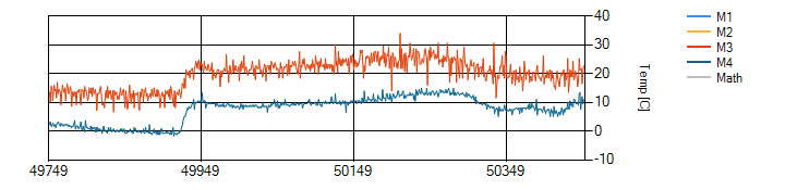
Apps: TDS298 & Slip21
Sampling period: 1min
Filename: H8dell2tmp
Sampling period: 1min
Date/Time: 1212140122 - 1212142106
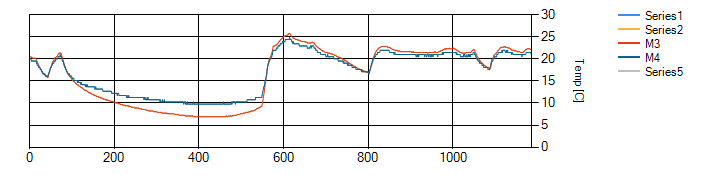
Filename: 4M1TDec15at23
Sampling period: 1min
I found the abnormal M4 output under 15°C, when I began measuring my room temperature by MCU averaging A/D inputs.
I stopped to work Slip21 and TDS298 and checked M4 output on my desk. It seemed that the sensor is different from my
order part model. When I opend the output from A/D input, the output value rised. I measured the value by DSO. I
doubted the load driving ability of the sensor. The data sheet describs to load 50uA. I calculated the output
impedance of source load. The equivalent resistor was 25kΩ! I thought that M4 indicated larger temperature than
M3 because the sink load impedance is rather big. It was lucky that I used LM358 OP amplifier. LM358 is dual type. I
decided the unused one as voltage follwer to lower output impedance. The below graph shows M3 temperature is the same
of M4 under 15°C, when the M4 offset is zero. It means that the senor model is different from my order one. The
lower temperature limit of the one on my board is 10°C.
I open my mother board circuit (3664.pdf) and hope that you will design another
circuit. My circuit is not best because I used limited parts in my part box.
App TDS298
Board: Akizuki H8/3664F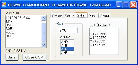
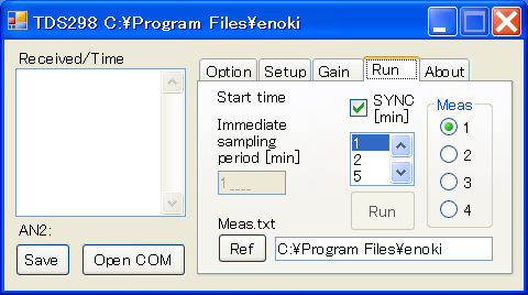
I always have measured charging battery voltage, the sun light power and room temperature at every minute. Room temperature usually does not vary at every minute, some users may measure some data at 2 or more minutes. If someone will measure at every hour for a year, the record numger will be 8600. I have already confirmed that Slip21 recorded and drew more than 56k records measured by 1 minute sampling peiod. So I programmed TDS298 to select sampling period 1, 2, 5, 10, 20, 30 and 60 minute.

Biwa Lake JAPAN aboutMe
© 2012 Enoki